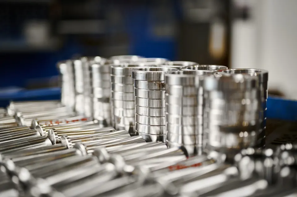
Capability source: each operation is confirmed per project as in-house or through qualified partners in our manufacturing network.
Typical applications
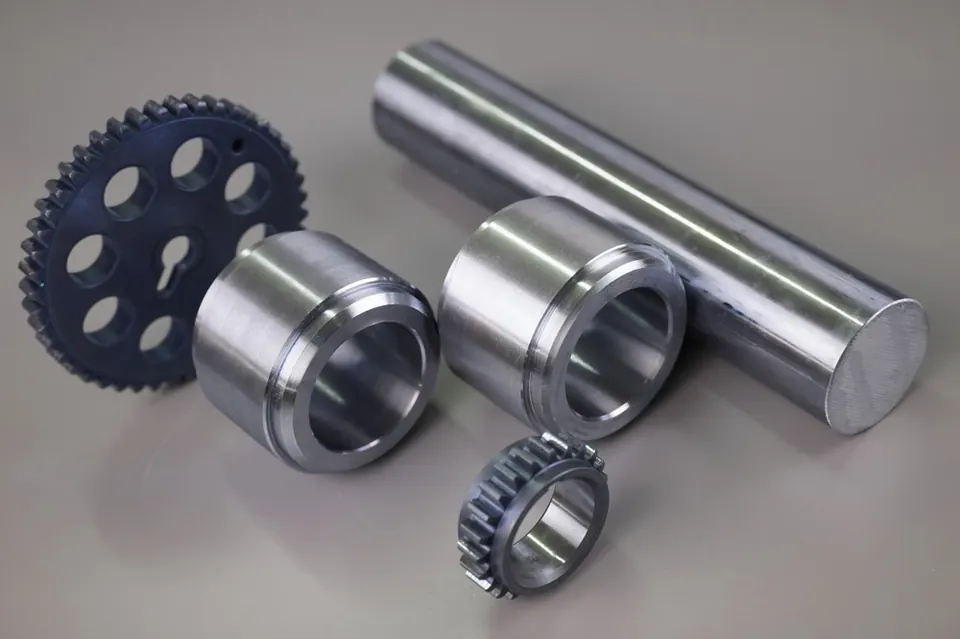
- Plain and flanged bearing bushings
- Guide sleeves, liners and wear sleeves
- Spacers and distance pieces in shaft assemblies
- Rings, washers, shims and discs
- Drill bushings and jig components
- Insulating sleeves in plastics
Machining processes
CNC turning
Outer diameter, bore, faces and grooves are turned, often complete in one clamping with parting off, so bore and OD stay concentric.
Sub-spindle or second operation
The back face and chamfer are finished on the sub-spindle or in soft jaws, which keeps both faces parallel.
Honing and reaming
Bores in H7 and below, or with a defined cross-hatch for lubrication, are reamed or honed.
Grooving and lubrication features
Oil grooves, lubrication holes and flats are turned or milled as part of the same set-up.
Materials
| Material | Why it is used |
|---|---|
| CuSn12 (CC483K) and other bronzes | Plain bearing bushings with good sliding and emergency running properties |
| CW614N / CuZn39Pb3 brass | Spacers, sleeves and fittings in high quantities |
| C45, 42CrMo4 | Load-bearing spacers and sleeves, hardened where needed |
| 1.4305 / 303, 1.4404 / 316L | Corrosion-resistant spacers and sleeves |
| POM-C, PA6, PTFE, PE1000 | Low-friction, insulating or chemically resistant bushings |
Dimensional and geometric requirements
| Feature | Typical requirement | How it is achieved and checked |
|---|---|---|
| Bore diameter | H7 (for example Ø20 H7 = +0/+0.021 mm) | Finish boring, reaming or honing; bore gauge or plug gauge |
| Concentricity bore to OD | 0.01–0.03 mm | Turned in one clamping; dial indicator or CMM |
| Face parallelism | 0.01–0.02 mm | Second-side facing or surface grinding; height gauge or CMM |
| Wall thickness | ±0.02–0.05 mm | Follows from bore and OD tolerances |
| Length / thickness | ±0.02–0.05 mm | Facing or grinding; micrometer |
NoteValues are typical drawing requirements for this part family and are confirmed for each drawing after engineering review.
Surface finish
Sliding bores are typically Ra 0.4–0.8 µm; faces of spacers in clamped stacks Ra 0.8–1.6 µm. Plastic bushings are machined with sharp tools and controlled heat to avoid smearing.
Quality and inspection
- Bore diameter checked with plug gauges or bore gauges at defined frequency
- Parallelism and thickness of spacers measured on a surface plate
- For thin-walled sleeves: roundness checked in the free state and, if specified, when assembled
- Plastic parts measured after conditioning, because dimensions move with temperature and moisture
What to include in your enquiry
Besides the drawing, 3D model, material and quantities, please state:
- Bore and shaft fit (for example H7/f7) and operating clearance
- Lubrication method and any oil grooves
- Press-fit interference if the bushing is pressed into a housing
- For plastics: operating temperature and media