Capability source: each operation is confirmed per project as in-house or through qualified partners in our manufacturing network.
Typical applications
- Machine and pipe flanges, blind flanges
- Hubs for gears, sprockets and pulleys
- Rigid and flexible shaft coupling halves
- Motor adapters and gearbox adapter plates
- Reducers and transition pieces
- Bearing caps and covers
Machining processes
CNC turning
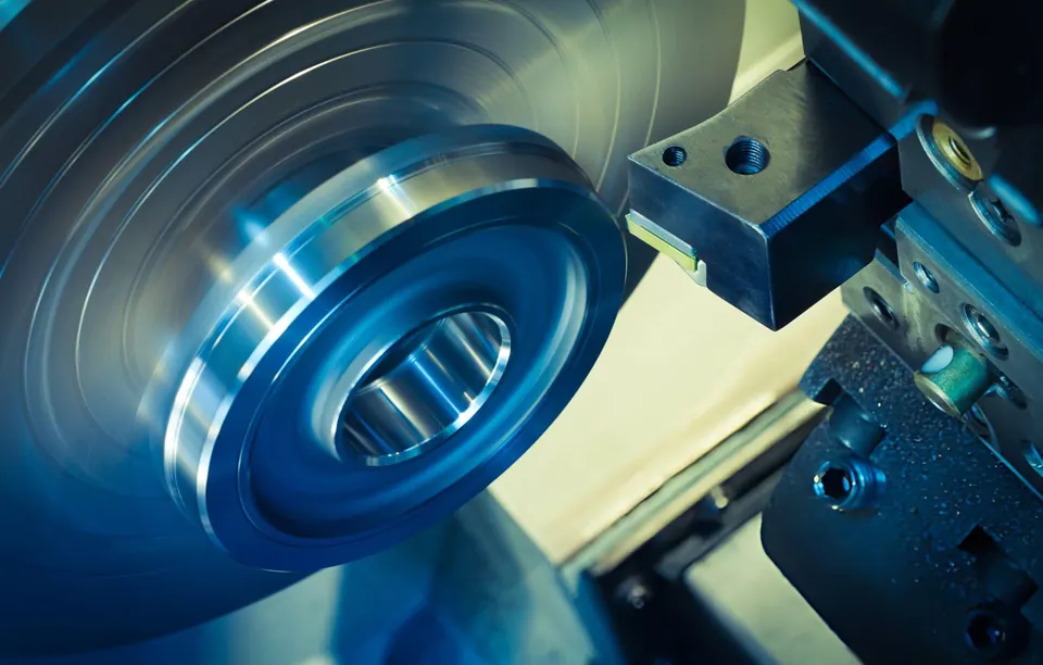
Bore, register (spigot), faces and sealing grooves are turned. Turning both faces in controlled set-ups keeps them parallel and square to the bore.
Mill-turn machining
Bolt-hole patterns, tapped holes and keyways are machined with live tools and the C-axis in the same clamping, so their position is tied to the bore.
CNC milling
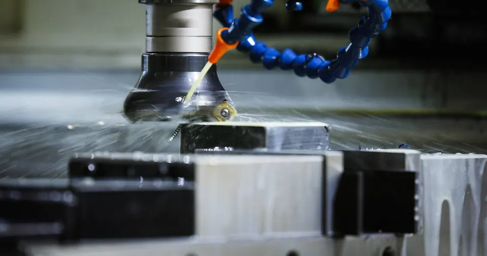
Larger or non-round flanges, adapter plates and coupling claws are milled on machining centres.
Broaching or slotting
Keyways in hub bores are cut by broaching, slotting or wire EDM through partners where required.
Materials
| Material | Why it is used |
|---|---|
| S355, P250GH, P265GH | Welded and pressure-retaining flanges (to the specified standard) |
| C45, 42CrMo4 | Hubs and couplings transmitting torque |
| 1.4301 / 304, 1.4404 / 316L | Corrosion-resistant flanges in process and food equipment |
| EN AW-6082 | Light adapter plates and motor flanges |
| Ductile cast iron | Machined cast hubs and flanges |
Dimensional and geometric requirements
| Feature | Typical requirement | How it is achieved and checked |
|---|---|---|
| Bore | H7 for hubs and couplings | Finish boring or reaming; plug or bore gauge |
| Bolt-circle position | Position Ø0.05–0.1 mm to bore and face | C-axis or milling in one clamping; CMM |
| Face flatness | 0.02–0.05 mm | Finish facing; surface plate or CMM |
| Perpendicularity of face to bore | 0.02–0.03 mm | Face and bore machined in one clamping; CMM |
| Register (spigot) diameter | h7 / H7 fit with mating part | Finish turning; micrometer or ring gauge |
| Sealing groove | Per O-ring standard (for example ISO 3601) | Form tool or grooving; optical or CMM |
NoteValues are typical drawing requirements for this part family and are confirmed for each drawing after engineering review.
Surface finish
Gasket and sealing faces are specified by the flange or seal standard — often Ra 3.2–6.3 µm with a concentric serrated or smooth finish; O-ring grooves are typically Ra 0.8–1.6 µm. Bores for hubs are usually Ra 1.6 µm.
Quality and inspection
- Bolt-circle position and face perpendicularity measured on CMM against the bore datum
- Sealing faces checked visually and for flatness
- Tapped holes gauged; thread depth verified
- For pressure equipment: material traceability and certificates as required by the applicable standard
What to include in your enquiry
Besides the drawing, 3D model, material and quantities, please state:
- Flange standard (for example EN 1092-1, ASME B16.5) or full drawing
- Sealing face finish and gasket type
- Datum structure: bore, face and bolt circle
- Pressure-equipment requirements, if any