Capability source: each operation is confirmed per project as in-house or through qualified partners in our manufacturing network.
Typical applications
- Drive, gearbox and pump shafts
- Axles, spindles and rollers shafts
- Dowel, hinge, pivot and locating pins
- Threaded shafts, studs and tie rods
- Motor and actuator output shafts
- Cam and eccentric shafts
Machining processes
CNC turning
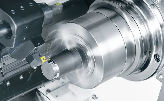
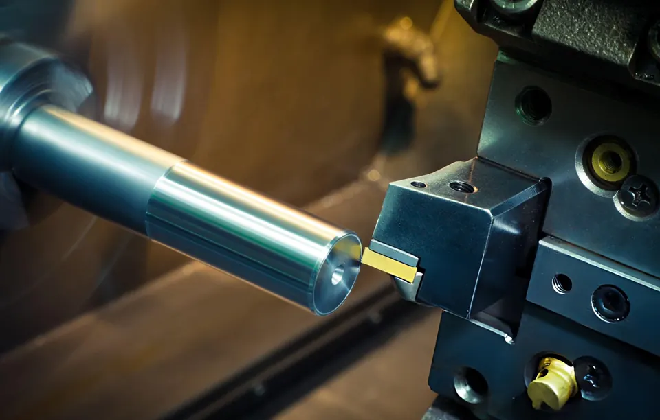
Diameters, shoulders, grooves, chamfers and threads are turned from bar or forged blanks. Long shafts (length over about 4–6 × diameter) are supported by tailstock or steady rest.
Mill-turn machining
Keyways, flats, cross holes and radial threads are milled in the same clamping, which keeps them aligned with the turned axis.
Cylindrical grinding
Bearing seats and seal diameters that need IT5–IT6 or Ra below 0.4 µm are ground between centres after turning and, if specified, heat treatment.
Heat treatment and coating
Through-hardening, case hardening, induction hardening, nitriding or hard chrome are coordinated with qualified partners and specified on the drawing.
Materials
| Material | Why it is used |
|---|---|
| C45 / 1.0503 | General-purpose shafts; can be induction hardened on bearing seats |
| 42CrMo4 / 1.7225 | Highly loaded drive shafts, usually supplied quenched and tempered |
| 16MnCr5 / 1.7131 | Case-hardened shafts and pins with wear-resistant surfaces |
| 11SMnPb30 / 1.0718 | Free-cutting steel for small pins in larger quantities |
| 1.4404 / 316L, 1.4305 / 303 | Corrosion-resistant shafts for food, marine and pump applications |
| EN AW-6082, EN AW-7075 | Light shafts and pins where weight matters more than wear |
Dimensional and geometric requirements
| Feature | Typical requirement | How it is achieved and checked |
|---|---|---|
| Bearing seat diameter | IT6 (for example Ø30 k6) | Finish turning or grinding; micrometer or air gauge |
| Run-out between seats | 0.01–0.02 mm | One clamping or ground between centres; dial indicator on V-blocks or centres |
| Cylindricity of seats | 0.005–0.01 mm | Grinding; CMM or form tester |
| Keyway width and position | P9 / N9 width, symmetry 0.02–0.05 mm | Milled in the turning clamping; gauge block and CMM |
| Thread | 6g (metric), 2A (UN) | Thread turning or rolling; ring gauges |
| Length and shoulders | ±0.05–0.1 mm | Turning; height gauge or CMM |
NoteValues are typical drawing requirements for this part family and are confirmed for each drawing after engineering review.
Surface finish
Bearing seats typically call for Ra 0.4–0.8 µm and seal running surfaces Ra 0.2–0.8 µm without lead (spiral) marks — achieved by plunge grinding. General turned diameters are usually Ra 1.6–3.2 µm.
Quality and inspection
- Run-out and concentricity measured relative to the functional datums on the drawing
- Diameter and roundness of bearing seats measured at several sections
- Hardness and case depth verified after heat treatment where specified
- Thread gauging (go/no-go) on every threaded feature in the inspection plan
- Material certificates to EN 10204 3.1 on request
What to include in your enquiry
Besides the drawing, 3D model, material and quantities, please state:
- Datum axis (bearing seats A–B) and run-out callouts
- Heat treatment, hardness and case depth
- Surface requirements for seal surfaces (Ra, no lead)
- Straightness requirement for long shafts