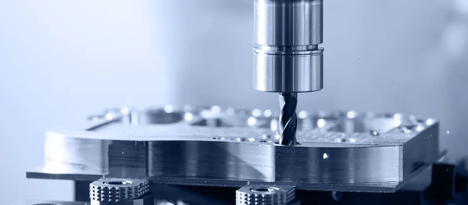
Internal corners
Milling cutters are round, so internal vertical corners always have a radius. Design corner radii slightly larger than the tool radius — this lets the cutter move smoothly instead of stopping in the corner.
Rules of thumb
| Feature | Recommendation | Why |
|---|---|---|
| Internal corner radius | ≥ 1/3 of pocket depth where possible | Allows stiff tools |
| Pocket depth | ≤ 4 × tool diameter for standard tools | Deflection, chatter |
| Wall thickness (metal) | ≥ 0.8–1.5 mm depending on height and material | Vibration, distortion |
| Wall thickness (plastic) | ≥ 1.5–2 mm | Flexibility, heat |
| Hole depth (drilled) | ≤ 10 × D for standard drills | Straightness, chip evacuation |
| Thread depth | 1.5 × D in steel is usually enough | Strength gained beyond is small |
| Small holes | ≥ ⌀1 mm unless essential | Tool breakage |
| Text and engraving | Engraved, not embossed; ≥ 0.5 mm stroke | Small tool life |
Reduce set-ups
Each set-up adds handling, re-clamping error and time. Group features by machining direction, give the part a stable clamping face, and avoid features on every side when they are not needed.
Tolerances and surfaces
- Use general tolerances (ISO 2768 or ISO 22081) for non-functional dimensions.
- Apply tight IT grades only to fits and functional interfaces.
- Use GD&T to describe function — position instead of chained ± dimensions.
- Specify roughness only where it matters, and with the right parameter.
Material and stock
Designing around standard bar and plate sizes reduces material cost and waste. For larger quantities, ask whether a casting or forging blank would be more economical — see integrated manufacturing.