How turning works
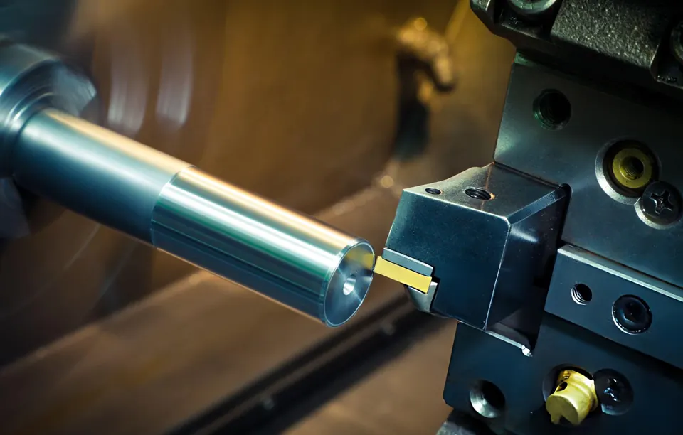
A CNC lathe holds the part in a chuck or collet and rotates it; the tool moves along the Z axis (parallel to the spindle) and the X axis (diameter). Bar-fed lathes produce parts from bar continuously, while chucking work handles forgings, castings and larger diameters.
Cutting data and surface finish
In turning, the cutting speed is set at the diameter being cut; modern controls keep it constant as the diameter changes (constant surface speed, G96). The theoretical surface roughness depends on feed and nose radius:
- Theoretical peak-to-valley
- Rt ≈ f² / (8 · rε)
- Example
- f = 0.15 mm/rev, rε = 0.8 mm → Rt ≈ 3.5 µm, Ra ≈ 0.9 µm
- Wiper inserts
- allow about double the feed for similar finish
- Calculator
- turning calculator
Real roughness is higher than theory because of tool wear, vibration and material behaviour, so finishing parameters are confirmed on the first part.
Workholding
- Collets for bar work: concentric and fast.
- Hydraulic chucks with soft jaws bored to the part diameter for accurate second operations.
- Tailstock and steady rests for long, slender shafts (L/D above roughly 4–6).
- Sub-spindles to machine the back of the part without manual re-clamping.
Tolerances you can expect
Diameters in IT7 are routine on well-maintained lathes; IT6 and run-out below 0.01 mm are achievable on suitable parts with controlled finishing. Tighter requirements may call for grinding. Always specify run-out or coaxiality to the functional datum rather than relying on diameter tolerances alone.
Typical turned parts
- Drive and pump shafts
- Bushings and spacers
- Flanges and adapters
- Hydraulic and pneumatic fittings
- Threaded connectors
- Valve stems and seats